5 Types of Drawings Used In Building Construction
Construction drawings serve an important purpose in building construction. Usage of these two-dimensional depictions may include documenting existing conditions, proposing modifications, quantifying materials, and assessing compliance with local building codes. Construction drawings are critical to document owner expectations, communicate design intent and recommend work broken down by trade or discipline. Without them, visualization of the final project is impossible.
There are different types of construction drawings, and it could be confusing for someone without a construction background to differentiate all of them. Below are the five types of drawings used in building construction.
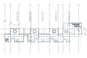
1. Architectural Drawings
Architectural drawings detail the purpose of the space, how it is perceived, and how the occupant interacts with it. Efficient use, comfort and safe egress are documented on these sheets. These drawings may also give a preview of other aspects of the design that will be documented in more detail by other design disciplines. Common drawings or details may include: floor plans, elevation views, building sections, wall details and other vital details. Architectural drawings are often created using 2D or 3D architectural design software.
Architectural drawings specify general arrangement and a background of the facility. As background images, these drawings are often shared with other design professionals for them to quantify fees and detail discipline's specific features. These drawings are also critical for resolving issues prior to the actual construction. Architectural drawings (or BIM models) are often used for performing location collaboration and clash detection with other disciplines. Without architectural drawings, there would be no clear directive on a building’s design, increasing the likelihood of change orders and budget overruns.
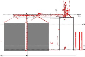
2. Structural Drawings
Structural drawings are engineering documents that focus on detailing the building’s support features. A structural drawing may include the size and type of members; dimensions for a concrete structure; information and details about reinforcement bars; and other data that affects construction.
3. Electrical Drawings
Sometimes called wiring diagrams, electrical drawings give a visual description of the electrical systems in a building and how they connect to the outside power grid. The purpose of an electrical drawing is to explain the electrical design to the electricians installing the system. It will also be used as a reference for future electrical repairs. Electrical drawings fall into one of several types: schematic, wiring, block and pictorial.
4. Sanitary and Plumbing Drawings
A plumbing drawing provides a visual representation of the building’s plumbing system. It includes the exact location of pipes, valves and fixtures; and outlines how freshwater is supplied and how wastewater is discharged. This type of drawing is used to illustrate the engineering design to those contractors installing the structure’s plumbing system.
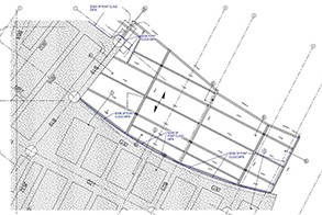
5. As-Built Drawings
As-built drawings, or finished drawings, document the actual final construction completed. As-built drawings may look different from the initial architectural and structural drawings since most designs need adjustments along the way. Regardless, as-built drawings are intended to document final construction. Since most architects and engineers are not involved in the day-to-day processes and are not aware of the changes made during construction, it is often up to the contractors to submit final as-built drawings. The nature of this final process makes initial as built documents unreliable without laser scanning after construction is complete.
Conclusion
A construction project is a rather complicated one that involves a lot of work both before and after the actual construction. To complete a building construction project, different types of drawings are needed.
An architectural drawing, perhaps including a computer-rendered 3D architectural design, is needed first. Then, based on the initial architect’s plan, a structural drawing is submitted. After that, wiring and plumbing diagrams convey the design to the workers installing these systems. Lastly, an as-built drawing is compiled by the contractors to show the final project, including any changes and adjustments done to the initial design. Another way to capture the final as built drawing is by 3D laser scanning the project site.