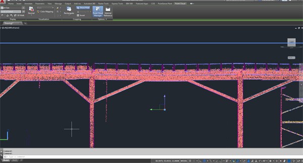
Cross section of colorized point cloud in AutoCAD showing settlement of column line
Case Study: Historical Amusement Park Building
Location: Sandusky, Ohio
Task: Scan the interior of a building of historical significance constructed in the late 1800s and modified in the mid 1900s with an added second story. Support Columns and Beams on the first floor were the focus of the scan in order to analyze the building’s structural integrity and bring it up to current required building and loading codes.
Challenge: The client was going to set new steel column and beams and needed to determine the absolute minimum clearance between all of the various column bays. If the sheer number of bays was not overwhelming enough, trying to determine which bay had the lowest elevation was even more difficult. Using a tape measure, the client was trying to measure the height of the support beams from the floor. However, since the floor was old and had a great deal of undulation (elevation changes), it was difficult to determine which bay had the lowest beam. In addition, this was only one or two measurements per bay and was prone to inaccuracies related to using a tape measure. In addition, this only provided the minimum clearance of each bay and did not identify the bay with the overall lowest elevation. Traditional survey methods could have been used, but that would have been timely and still limited to one or two measurements per bay.
Solution: By utilizing 3D Laser Scanning, the entire interior space could be captured in just one day, providing millions of measurements along the floor, columns and beams. And since all of the scan data points are x, y, z coordinates that are relative to each other, all of the column bays can be compared to the other to determine which beam had the lowest overall elevation, independent of the floor elevation, throughout the facility. This allowed the client to then know what height the new steel needed to be set.
Deliverables: Colorized Point cloud and AutoCAD files (.dwg file format) with Section Views of each column line showing the lowest spot elevation on the beams and highest spot elevation on the floor of each column bay, as well as the lowest beam elevation over the entire structure.
Added Value: In addition to deformation around the columns and beams, floor topography could be analyzed as well. A color elevation map of the floor surface was provided to show floor flatness and potential areas of concern. TruePoint’s staff of Engineers, Architects and Technical professionals are able to offer additional insight into potential problems.
If you have a building renovation, historical preservation, urban planning, façade restoration project or other laser scanning needs, contact TruePoint Laser Scanning at 216-470-7262 or cleveland@truepointscanning.com to discuss your project needs.
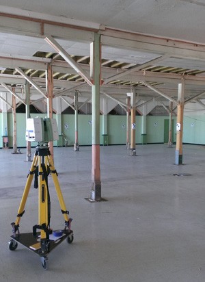
3D Laser Scanning of Interior Space
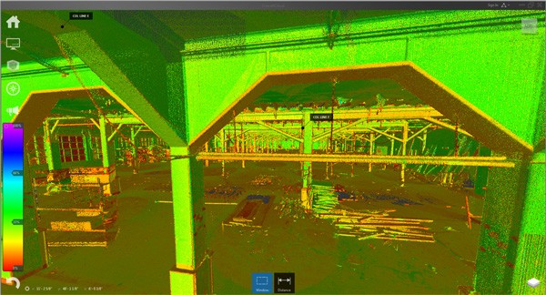
Colorized point cloud in Autodesk Recap
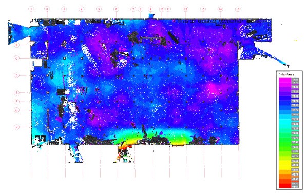
Floor Elevation Map
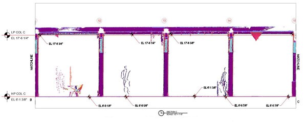
2D AutoCAD drawing of a column line showing overall lowest frame elevation, highest floor elevation and spot elevations of each individual column bay
